Before installing components into a carburetor, one should have a good knowledge about the components, clean them, inspect them, and repair or replace them as is necessary.
Main Jet

- The Main Jet delivers the major portion of the fuel to the engine at 30 plus MPH.
- When installed with a washer, its tip should be level with the Lower Casting shelf that the Venturi sits on. So, when you remove a Main Jet, make sure you also dig out the old gasket. If you end up with multiple gaskets installed, it will cause poor performance and leaks, because the Jet tip isn't precisely where it should be in the Venturi.
- The Jet needs to have an indented (dished out) tip, to prevent capillary action leaks when engine is off.
- Original Jets were marked with a number to signify orifice size. From Oct 1927 through June 1928 they were numbered "20", which was 0.0394" diameter. From July 1928 through 1929 they were numbered "19.5", which was .0384" diameter. From 1930 through 1931 they went back to a number "20".
- To resize jet orifice: Heat jet at orifice end and fill with solder (Do not over heat or fill beyond 1/8" deep with solder). Carefully remove solder from indented area with a 5/64" drill, using a pen vise (not a drill motor). Carefully drill out orifice (With pen vise! Do not use drill motor) and clean out with air pressure.
- The issue is that the best flow should be 150 to 160 milliliters per minute, at the atmospheric pressure that your driving at.
- However, a little better engine performance, at the sacrifice of miles per gallon, can be accomplished by drilling the main jet with a #61 or #60 drill (170 to 185 milliliters per minute).
- I definitely recommend flow testing of jets, particularly those that have been soldered and drilled.
- Very good instructions for doing jet flow testing can be found in "Zenith Model 'A' Carburetor Restoration Guidelines".
- The Main Jet is usually the cause of high-speed carburetor problems.
- If the orifice is too large, the excessive flow will result in: A rich mixture, low mileage, sooty plugs, smell of gas and irregular running.
- If the orifice is too small or restricted, the insufficient flow will result in: A lean mixture, reduced high speed, and it might even cause backfire at high speed.
- Bullet shaped tips are notorious for causing low flow leaks when vehicle is parked.
- The threads are M5 x .75 (Metric)
ˆ Top of Page
•
Gaskets
Cap Jet

- The cap jet delivers most of the fuel at low speed driving.
- It gets its gasoline from the Compensator Jet and the gas Adjusting Valve.
- It is removed from the lower casting with a 5/16" nut driver
- When installed with a gasket washer, it's tip should be level with (to 1/16" below) the lower casting shelf that the Venturi sits on.
- Jet needs to have an indented (dished out) tip.
- Original jets were marked with a number to signify orifice size. From Oct 1927 through June 1928 they were numbered "19", which was 0.0374" diameter. From July 1928 through 1929 they were numbered "21", which was 0.413" diameter. From 1930 through 1931 they were numbered "20", which was 0.0394" diameter.
- I recommend that orifice is drilled with a #62 drill. (That's 38 thousands of an inch).
- To resize jet orifice: Heat jet at orifice end and fill with solder (Do not over heat or fill beyond 1/8" deep with solder). Carefully remove solder from indented area with a 5/64" drill, using a pen vise (not a drill motor). Carefully drill out orifice (With pen vise! Do not use drill motor) and clean out with air pressure.
- The flow should be in the range of 170 to 190 milliliters per minute, but is not critical.
- If the jet is too small or restricted, the insufficient flow will cause a lean mixture and miss or jerk on hard pulls at low speed.
- The threads are M5 x .75 (Metric)
- Occassonally, the cap jet is broken off due to over tightening. It is best to remove a broken cap jet by starting with a small drill and then sequentially using larger drills to slowly drill away the barrel of the jet. Be careful not to destroy the castings threads and clean the brass out of the threads with a M5 x .75 (Metric) tap. Sometimes brass debri may need to be picked out of the casting.
ˆ Top of Page
•
Compensator Jet
•
Gaskets
•
Main Jet or Cap Jet Tip is not "dished" / "indented".
•
Small Drill Sets
•
Jet Flow Testing Setup
Compensator Jet
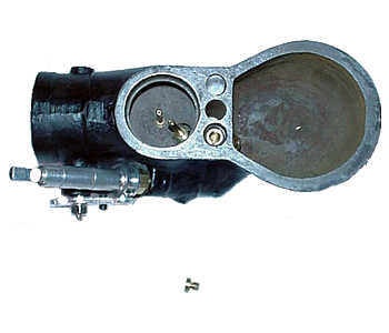
- The Compensator Jet compensates for the enriching effect of the Main Jet as airflow increases and it thus provides a more constant air to fuel mixture.
- The compensator Jet is the only component in the main well of the lower casting.
- The jet should be installed with 2 gasket washers, since on some casting and secondary well combinations the jet will come into contact with the brass secondary causing restricted flow.
- Original jets were marked with a number to signify orifice size. From October 1927 through June of 1928 they were numbered "18", which was 0.03543" diameter. From July 1928 through 1931 they were numbered "19", which was 0.0374" diameter.
- I recommend that orifice is drilled with a #63 to #64 drill, which is 37 - 36 thousands of an inch.
- To resize jet orifice: Heat jet at orifice end and fill with solder (Do not over heat or fill beyond 1/8" deep with solder). Carefully remove solder from indented area with a 5/64" drill, using a pen vise (not a drill motor). Carefully drill out orifice (With pen vise! Do not use drill motor) and clean out with air pressure. When soldering and drilling orifice of this jet, be cautious of leaving solder in the screwdriver slot area. A screwdriver can move the solder, when jet is installed, reduce the orifice opening.
- The flow should be between 155 and 165 Milliliters per minute.
- I particularly recommend flow testing of jets that have been soldered and drilled.
- If jet is too large, the excessive flow will cause irregular running at low speeds. The excessive flow also causes low mileage, sooty plugs, and smell of gas.
- If the jet is too small or restricted, the insufficient flow will cause a lean mixture and miss or jerk on hard pulls at low speed.
- The threads are M5 x .75 (Metric).
ˆ Top of Page • Gaskets • Secondary Well • Small Drill Sets • Jet Flow Testing Setup
Secondary Well
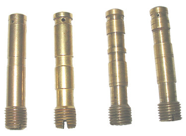
- The Secondary Well provides an extra shot of gasoline instantly when the throttle is opened rapidly.
- The in flow of extra fuel at low speeds takes care of an otherwise lean mixture that would occur just off idle.
- There were several variations of Secondary Well designs, with the undercut in different locations. In some combinations of castings and secondary wells, the compensator jet will come into contact with the brass secondary causing restricted flow. So, I recommend that 2 gasket washers be used with this jet to prevent that possibility.
- With really dirty carburetors, the secondary well main bore and all of the small holes may need to be cleaned out.
- The small hole in one side is a #70 drill size, but it's not critical. The hole is referred to as the "vacuum breaker" hole.
- The small hole that goes through both sides is a #54 drill size, but it is not critical.
- The secondary well threads are 3/8x24 UNF (SAE).
Idle Jet
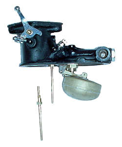
- The Idling Jet provides gasoline (from the Secondary Well) to the engine at idle.
- Original Jets were marked with a number to signify orifice size. From Oct 1927 through June 1928 they were numbered "10", which was 0.0197" diameter. From July 1928 through 1931 they were numbered "11", which was 0.0217" diameter.
- I recommend that orifice is drilled with a #74 to #75 Drill. (That's 0.0225 - 0.0210 inch).
- To resize jet orifice: Heat jet at orifice end and fill with solder (Do not over heat or fill beyond 1/8" deep with solder). Carefully remove solder from indented area with a 5/64" drill, using a pen vise (not a drill motor). Carefully drill out orifice (With pen vise! Do not use drill motor) and clean out with air pressure.
- The flow should be between 44 and 48 milliliters per minute.
- I particularly recommend flow testing those that have been soldered and drilled.
- This is a very small orifice hole and flow. It's easily clogged by dirt, rust, etc.
- If the jet is too large, the Air Adjustment Screw will need to be turned out very far.
- If the jet is too small or restricted, it will be impossible to obtain a satisfactory mixture, except by turning the Air adjustment screw all the way in.
- Some carburetors, on some engines, need to have the Idle Jet slightly larger or smaller than a #74 Drill.
- No washer is used with this jet because it is a taper fit.
- Watch for fractures / breaks along the shaft and stems that turn in its base.
- The total length of an Idle Jet is 3 inches.
- If you run across one that is longer than 3 inches, it's a little rare, and it belongs to a Zenith Carburetor with a Double Venturi. The Double Venturi carburetor did not originally use a Brass inserted secondary well, so to compensate, the Idling Jet was made a little longer. Less than 5% of the carburetors made were Double Venturi.
- The threads on the idling jet are M5 x .75 (Metric)
ˆ Top of Page • Secondary Well • Small Drill Sets • Jet Flow Testing Setup • Venturi
Castings

- The Castings are made of Cast Iron and are prone to rusting. Sometimes they can get very dirty and rusty.
- Bead blasting of castings is the best way to clean them up.
- Passages with flow restriction cause all kinds performance headaches. Passages must be cleaned out. To do so, passage plugs often must be drilled out and later replaced. See Removing and Replacing Brass Passage Plugs. Give the passages special care in cleaning and inspecting. See Fiber Optic Light.
- Occasionally, the taped holes for jets are damaged to the point that they must be repaired. See .
- The mating surfaces of the two carburetor castings must be flat, free of burrs, and not have deep scratches. Use stone to remove any high spots. Scratches can be filled with JB Weld and when hardened sanded flat.
- The upper casting, throttle bushing area must not be worn out of round, causing vacuum leaks. To repair worn throttle bushing hole, use Throttle Shaft Bushing Drill Fixture Plate.
- When cleaning, the casting threads should be chased. See Casting Threads.
- Fuel Inlet port must mate smoothly to fuel line ferrule. See Dremel Stone #911.
- Inspect castings carefully for cracks in castings near Fuel Inlet and GAV.
- Bead blasted castings should be painted with POR-15 Semi-gloss Black paint for compatibility with high temperature and gasoline. Do not apply paint to anything brass or cad plated (i.e. plugs, stop pins).
ˆ Top of Page • Fiber Optic Light • Throttle Shaft Bushing Drill Fixture Plate • Casting Threads • Dremel Stone #911
Upper Casting Passages
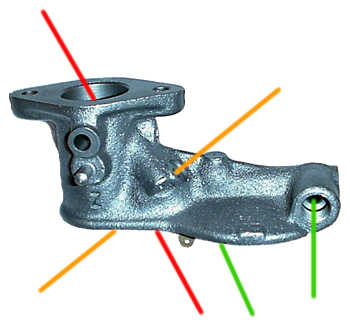
- Casting Passages for the flow of gasoline and air are critical "Components" of the carburetor that are often overlooked. Sections of some passages had to be drilled via the outside surface of the casting. Then the ends were filled with brass plugs. When rebuilding carburetors, I recommend that the plugs be drilled out, passage cleaned out, and then re-plugged. These Brass plugs are available at most Model A parts suppliers.
- The Green line identifies the large passage for gasoline to get to the Float Bowl from the Fuel Input Line, via a Passage through the Strainer and Float Valve. In addition to this passage clogging and fuel lines clogging, Strainers do deteriorate, with particles getting into Jets, etc.
- There's a small Idle Port in the throat, just above the closed, Throttle plate. The Red line notes that there's a gasoline Passage from the idle jet opening to the Idle Port in the Throat. This port provides gasoline and air at idle conditions via passages.
- The Orange line identifies air Passage from just to the rear of the Idle Jet opening that goes to the Idle Port, via the Air Adjust Screw.
- It was found that the Float Bowl needs to be vented to atmosphere to prevent conditions that could affect Float Valve operation. There's a small Air Vent Passage between the area above the Float Bowl area and the area just above the Secondary Well.
ˆ Top of Page • Fiber Optic Light
Lower Casting Passages
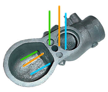
- Casting Passages for the flow of gasoline and air are critical "Components" of the carburetor that are often overlooked. Sections of some passages had to be drilled via the outside surface of the casting. Then the ends were filled with brass plugs. When rebuilding carburetors, I recommend that the plugs be drilled out, passage cleaned out, and then replugged. These Brass plugs are available at most Model A parts suppliers.
- The Blue line identifies the Passage that provides gasoline to the Main Jet from Float Bowl. It is connected via the Drain Plug opening. If this passage is restricted too much, it can cause a lean mixture at high speeds.
- The Orange line identifies the Passage that provides gasoline to the Cap Jet from the Float Bowl. It is connected via the Compensator Jet opening, and through the Secondary Well. On some castings, the passage was drilled straight through to the bottom of the cap jet. On other castings, the passage may make a jog when going from the secondary well to the bottom of the cap jet. If the passage is restricted too much, it can cause a lean mixture at low speeds.
- The Green line identifies the Gas Adjusting Valve Passages which provide additional gasoline to the Cap Jet. On most castings, the passage from the top of the GAV seat goes to the secondary well, and then to the bottom of the cap jet. However, on others, the passage goes from the top of the GAV seat directly to the bottom of the cap jet. If these passages are restricted, Opening the GAS Adjusting Valve does NOT provide any extra fuel at low speeds. This passage from the Float Bowl is the lowest and most likely to collect sediment. It's the passage that I find most likely be totally blocked.
- It was found that the Float Bowl needs to be vented to atmosphere to prevent conditions that could affect Float Valve operation. On Lower Castings (After mid 1930) there is an air vent.
ˆ Top of Page • Fiber Optic Light
Casting Threads
- Fuel Line input port, in upper casting, has 1/2-20 UNF (SAE) threads
- Fuel Screen Assembly, in upper casting, has 1/2-20 UNF (SAE) threads
- Float Valve, in upper casting, has 1/2-20 UNF (SAE) threads
- Main Hex bolt hole, in upper casting, has 3/8-24 UNF (SAE) threads
- Drain Plug hole, in lower casting, has 3/8-24 UNF (SAE) threads
- Secondary Well hole, in lower casting, has 3/8-24 UNF (SAE) threads
- Carburetor Mounting holes (2 places), in upper casting, has 5/16-18 UNF (SAE) threads
- Gas Adjusting Valve (GAV) hole, in lower casting, has 1/8-27 NPT (Pipe) threads. Use caution not to cut threads deeper, as it is a pipe thread.
- Air Adjust Screw hole, in upper casting, has M5x.75 (Metric) threads
- Main Jet hole, in lower casting, has M5x.75 (Metric) threads
- Cap Jet hole, in lower casting, has M5x.75 (Metric) threads
- Compensator Jet hole, in lower casting, has M5x.75 (Metric) threads
- Idle Jet hole, in upper casting, has M5x.75 (Metric) threads
- 5/16-18 and 3/8-24 threads which are stripped can be repaired. See Heli-Coil Thread Repair Kits and Installing Heli-Coils
- Idle Jet, tapped hole, must provide for taper fit.
ˆ Top of Page • Heli-Coil Thread Repair Kits
Throttle Assembly
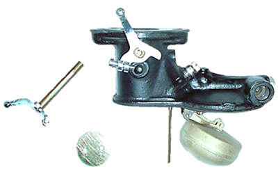
- The Throttle Arm / Shaft / Plate assembly controls the flow of vacuum that pulls gasoline and air into the intake manifold.
- Shaft and hole wear leads to vacuum leaks around the shaft, particularly on the arm end of the shaft. The most noticeable effect is poor idle. The soft metal of the shaft tends to wear faster than the casting hole.
- To address Shaft wear, replacement Throttle Shaft Assemblies are available from your suppliers.
- To salvage old arm styles, I build up the worn area with solder and turn down.
- If Casting hole is worn, drill out hole and press in bushings. Bushings are available from your suppliers. See Throttle Shaft Bushing Drill Fixture Plate.
- The Throttle Plate is attached to shaft with 2 Oval 5-40 UNF (SAE) thread x 19/64 screws
- Use high temperature grease on throttle shaft bearing surfaces to reduce friction, wear, and small air leaks.
- Idle Adjust Fillister Screws were 1/2" long until early 30 and then 5/8". The Fillister screw threads are 8-36 UNF (SAE). Off engine, initial setting of Fillister screw should slightly open the throttle plate.
- Some castings have the throttle shaft hole drilled through the back sides of the casting. If this is the case, a brass throttle shaft end plug (PN 9581-P) should be pressed in to prevent vacuum leaks.
ˆ Top of Page • Throttle Shaft Bushing Drill Fixture Plate
Idle Air Adjustment Needle Valve
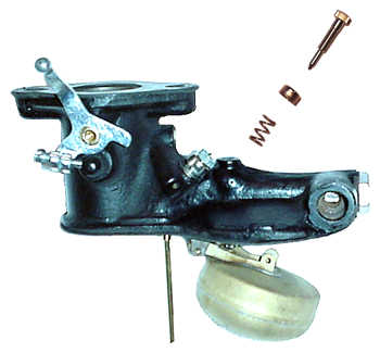
- The Idle Air Adjustment Screw controls the volume of air added and mixed with the fuel introduced through the Idling Jet to the Idle Port. The combination of Idling Jet and Air Adjustment Screw controls the idle air to fuel ratio. Remember, the Idling Jet receives its fuel from the Secondary Well that gets its fuel from the float bowl through the Compensator Jet.
- As the Air Adjustment Screw is turned in, the idling mixture is enriched due to less air being mixed with the idling jet gasoline. (Mixture is leaned down, as it is turned out)
- From factory the head diameter was 3/8" or .375" from 1927 through 1929; and 5/16" or .3125" 1930 through 1931. Through 1929, they were made of brass and thereafterm from steel.
- From factory the shaft lengths were 1 & 3/16" or 1.185".
- When restoring carburetors today I prefer needle shank length of 1 and 1/4 inches, to minimize risk of totally compressing the spring before valve is closed. There are some floating around that are a lot shorter, which causes the spring to collapse and stop before it can seat properly. If Air Adjust Screw Needle is too short or misadjusted, or if upper casting hole does not allow a good seat, the result will be an erratic idle.
- The threads are M5 X .75 (Metric).
- Loose air adjustment threads, in casting, can allow vacuum leaks and result in an irratic idle. This can generally be solved by applying high temperature grease on threads, or if leak is significant a small o-ring can be inserted between casting and spring.
- Off engine initial setting should be 1 & 1/2 turns from full clockwise.
ˆ Top of Page • Idle Jet
Gas Adjusting Valve (GAV) and Seat

- The Gas Adjusting Valve provides a manual adjustment for additional gasoline to the Cap Jet, bypassing the metering effect of the Compensator Jet. The carburetor was designed slightly lean to allow for high altitude driving and, with the GAV, is able to provide additional fuel as needed. This extra fuel is normally needed when the vehicle is cold and at low engine speeds.
- The threads on the needle and inside the housing are 1/4-24. Use 1/4-24 tap and die to clean up imperfect GAV housings and needles. Smooth running needles make for easier adjustments on the dash.
- A replaceable Brass Seat was used through 1929. An integral Seat, machined in the Lower Casting, was used after that. The Seat opening is honed to match the shape of the GAV Needle. Notice that the Brass GAV Seat looks much like the Compensating Jet. However, they are different! They are NOT interchangeable. The Brass Seat is also longer than a Compensator Jet. It is recommended to use a gasket under the brass seat.
- The Gas Adjusting valve housing nut used to install it, are made in two sizes (7/16" & 13/32"). To deal with the odd size, see Gas Adjusting Valve Wrench.
- The Gas Adjusting Valve housing's outside threads are 1/8" 27NPT (Pipe). Use Caution not to cut threads deeper, as it is a pipe thread.
- Carefully inspect the tapered end of the needle for wear ring caused by tightening it too tight. Damaged ones should be replaced.
- The GAV housing can become frozen in the pipe threads of the lower casting. The soft brass nut of the GAV is easily damaged beyond use. So, to remove such a GAV housing, cut the housing off just above the nut using a hacksaw. Then, remove the lower frozen part using a spiral screw extractor (Easy Out). Sometimes, they are really stubborn and have to be entirely drilled out.
ˆ Top of Page • Cap Jet • Compensator Jet • Gaskets • Gas Adjusting Valve Seat Honing Tool & Guide • Choke Driver with Wing Nut
Choke Arm and GAV Driver
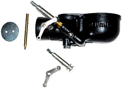
- This mechanism allows a single control to provide two functions that interact. It controls both the choke and gas adjusting valve.
- It is important that the Choke Arm Cam is well engaged into the GAV Driver. Some adjustment to reduce slop can be gained by loosening the two choke plate screws and pushing the choke arm in snuggly, and then retighten the screws.
- Choke Arm Cams wear and can cause binding of both Choke and GAV movement. A Bent Choke Arm can cause binding. Bent Choke Drivers and Rods can also cause binding.
- Choke shafts and choke arms must be compatible to insure that nuts neither bind nor provide sloppy fit. Early (28-29) Choke shafts had "steps" that were 0.165" long for the arms that were 5/32" thick. Later (30-31) Choke shafts had "steps" that were 0.13" long for the arms that were 1/8" thick.
- The nut which holds the choke arm on has 8/36 UNF (SAE) threads.
- The Choke Plate is attached to the shaft with 2 Oval 5-40 UNF (SAE) thread x 19/64 screws.
Float Valve and Float
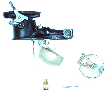
- Gummy residue from old gas in the bottom of a tank will cause continuing float valve problems, until tank is cleaned out.
- Float Valves must be very tight against their gasket or they leak, especially if casting threads are sloppy.
- When installing a valve, I recommend pushing the Valve Stem in hard and twisting a few times to seat it.
- The desired fuel level in the main well is 9/16 to 5/8 inches from the gasket surface of the bottom casting, with the engine not running.
- If the fuel level is set to 1/2" (from the gasket surface of the bottom casting, with the engine not running) it can allow some carburetors to stall when the vehicle comes to a quick stop. If the fuel level is less than 1/2" (from the gasket surface of the bottom casting, with the engine not running) it can allow some carburetors to drip gasoline from the air intake. If the fuel level is set greater than 11/16" (from the gasket surface of the bottom casting, with the engine not running) it can allow some carburetors to run lean mixture, with rapid acceleration.
- I prefer to use white neoprene gasket washers, which are .043 to .046 inches thick, under the float valves. The desired number to use under the float valve to obtain 9/16 to 5/8 inches of fuel in the main well varies with the valve design used.
- PN A9564-A Original type valve needs 1-2 washers.
- PN A9564-M Modern design valve with Neoprene seat needs 3 washers.
- PN A9564-Z Stainless steel ball, with O-ring seat needs 2 washers
- Sometimes, one needs to sand down a gasket washer thickness to get the float level set correctly. Measure the bowl fuel level using an external tube gauge. Most Model A parts suppliers carry them.
- The Float Valve threads are 1/2" 20 UNF (SAE)
- Inspect Float for a small dimple worn into the top of the float from valve needle rubbing. The effect of this dimple is a lateral bind on the valve needle that prevents it from closing completely and sealing.
- Floats can leak gasoline into them, and don't float very well.
- To pressure test Float for leaks, see Float Tester.
ˆ Top of Page • Gaskets • Float Tester
Gaskets
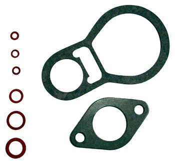
- Missing and dried out old Gaskets have caused numerous problems. They're very cheap! Replace them!
- Gaskets have to be cinched down tight to function properly. Sometimes after they soak up gasoline, Jets become loose. Some people recommend retightening after in use for a week. The red fiber gaskets are difficult to seal and I've seen cases where they are too thick. So, I have switched to a new carburetor gasket material that is now available. They are thinner, softer, and work better for sealing the jets. They are white or light blue in color and I think they are made from Neoprene. I have had no problems getting them to seal well.
Venturi
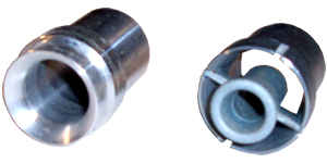
- The Venturi is a tube, which narrows to a small size and then widens out again, which increases the speed of the air rushing through the carburetor, and lowers its pressure. The higher air pressure in the float chamber then forces gasoline through the jets into the Venturi.
- The double Venturi was used from the start of production through June of 1928, and the single Venturi was then used until the end of production.
- The original, single Venturi had a .843" diameter throat, but many of the original Venturies are now warped from heat.
- Many of the newer Venturies, which are made of pot metal, measure .835 or less, and many have throats that are egg shaped by .010 or more.
- I like the quality, dimension, stability, and performance of the Snyder's Venturi. They consistently have an optimal opening at the narrow point of .845" to .847".
- Original Double Venturi assemblies were pinned into the castings. These pins need to be pressed out to extract the Venturi.
- A Venturi can be difficult to remove from castings. Heating the castings in an oven or with a torch often loosens them up. Also, see Venturi Extraction Tool.
Filter Strainer

- The Filter Strainer is an attempt to prevent rust and dirt from entering the carburetor.
- The Wrench head plug of strainer was Brass from 1927 - early 1930, and then was steel to the end of production.
- As castings have rusted and eroded, the strainer is not very effective. Much of the fuel flows around the end of the strainer versus through it.
- Filter Strainer is screwed in with a gasket washer using a 5/8" wrench.
Drain Plug

- Through 1929 the drain plugs were made from brass and were unfinished. Thereafter, they were steel and cad or plain finished.
- The threads are 3/8-24 UNF (SAE).
- The plug is installed, with a gasket washer, using a 1/2" wrench.
Main Bolt
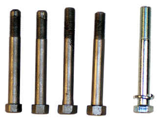
- The Main bolt has 3/8-24 UNF (SAE) threads.
- The hex head width was 1/2" through 1928. Thereafter, it was 9/16".
- The Hex head thickness was 5/16" through mid 1930 and 1/4" thereafter.
- Bolts were Cadmium or plain finished.
- A lock washer is used with the bolt.
- Bolts were originally 3 inches long.
- When restoring carburetors I prefer to use 3-3/16" bolts, since casting threads are sometimes damaged for the first 1/4".